Design Overview
Hardware
Temperature Sensor
The Omron D6T-8L-09 digital infrared thermometer was chosen for this project. This sensor works by continuously detecting radiant infrared energy and computing a temperature value from this. This is much better for our application than other non-contact thermometers like Pyroelectric sensors as they can only detect temperature changes and will not output a continuous and accurate temperature reading.
The viewing angles of the sensor are respectively:- X direction: 54.5°
- Y direction: 5.5°
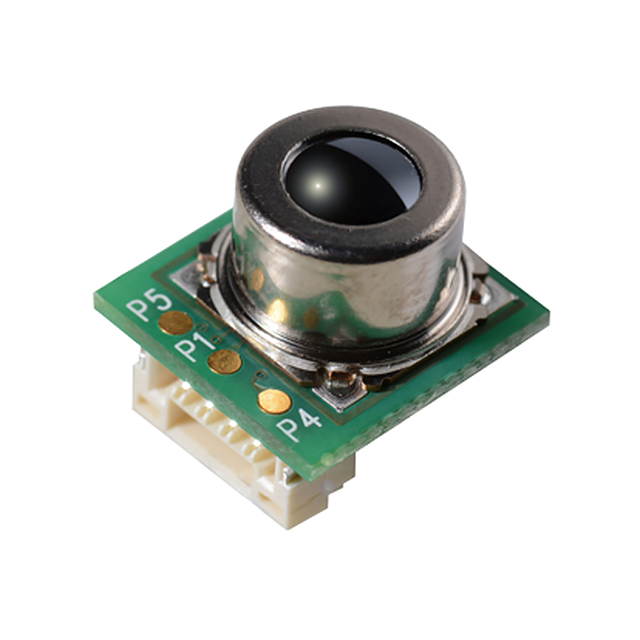 D6T-8L-09 Sensor
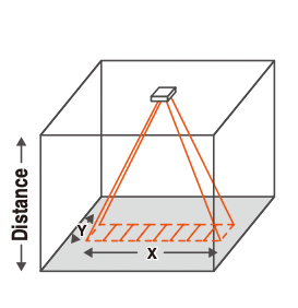 Viewing Angles
Servos
The next big challenge is given an x,y coordinate to move two servos; one for the x-axis and one for the y-axis to center the temperature sensor on that given point.
The way the coordinates worked from the camera side is that the frame is divided by the number of pixels in it with these rules:
- The upper left corner is point (0,0)
- The lower right corner is point (320,240)
- The center of the frame is point (160,120)
The way the servos were implemented is that they are moved based off of a given duty cycle. The duty cycle values are arbitrary with a value of 500 being at an angle of 0 (all the way left) by these rules:- A value of 500 is an angle of 0° (all the way left)
- A value of 2500 is an angle of 180° (all the way right)
- A value of 1500 is an angle of 90° (centered)
When the program is started the servos are centered at 1500. A calculation is done to find the distance from the forehead coordinate to the center of the frame in both the x and y direction:- xdistance = foreheadx-coordinate - 160
- ydistance = foreheady-coordinate - 120
These absolute values for both x and y are checked if they are then within a margin of error. Through trial and error we found about a 10x10 box that gave consistent results. This step is crucial as if there was no margin of error the servos would constantly overshoot the centerpoint and oscillate back and forth over it. If xdistance or ydistance is greater than the margin of error the servos are then moved either left/right or up/down in the direction of the centerpoint.
The amount they moved was arbitrarily set to be a value of 5 which corresponds to ~5°. This process is then repeated until the centerpoint is reached. Below is a visual representation of the frame and error box and a flowchart for the code.
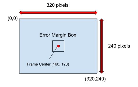 Frame Representation
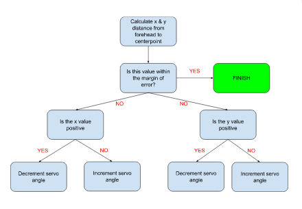 Flowchart
Ultrasonic Sensor
The HC-SR04 ultrasonic sensor was chosen to act as a distance sensor for A.T.T. It provides distance measurements between the ranges of 2cm to 400cm. The way the module works is by sending eight 40kHz signals and waits for a pulse signal back to determine the distance. The timing diagram for the sensor depicts the trigger input required and the echo pulse that’s received by the module. Below is an image that showcases the signals.

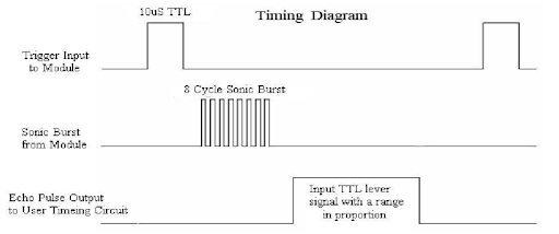 Timing Diagram
Liquid Crystal Display (LCD)
The 2x16 Liquid Crystal Display was chosen to help guide the user to an optimal temperature tracking distance with live feedback displaying the distance from the sensor, and after measurement, their recorded temperature.
The LCD was connected to the Raspberry Pi to receive signals that carried the temperature and distance data and fed to the display. The connections for the LCD were as follows:
- RS (Reset) connected to GPIO 22
- EN (Enable) connected to GPIO 17
- D4 - D7 connected to GPIO 18, 23, 24, 25
- 5V Vcc Input
 LCD Display
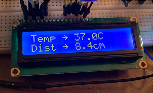 Contrast Adjusted Display
Physical Structure
Mechanical Casing
Another major part of the project was designing the enclosure for the components and designing the mechanical framework that would secure all the sensors and servos into place so they may perform their intended function. Each part was designed using Solidworks, along with each component’s appropriate measurements to ensure that each component will fit properly in their respective places.
The first component designed was the main box module seen in the image below where the main components such as the Raspberry Pi and the breadboard will be located, along with all the wiring connecting to the sensors and other components. This is to ensure that they will remain intact and provide an aesthetically pleasing outside appearance by avoiding all the complex wiring to be seen by the users. Located in the front of the box are two exterior cuts that will allow the ultrasonic sensor and the LCD displaying the user’s temperature and distance away from the device to pass through.
The image below displays all the necessary dimensions of the box that contains all the boards. The box’s dimensions (190mm X 100mm X 100mm) were carefully chosen so that the Raspberry Pi and the breadboard (85mm by 56mm and 65mm by 50mm respectively) can easily fit inside the container while having excess space for wiring for all the components.
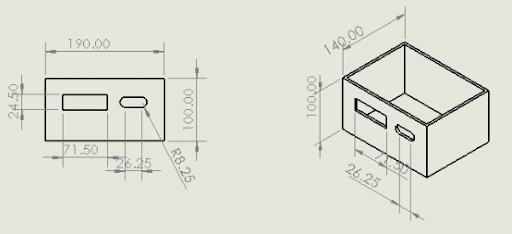 Main Box Module
The next part to be considered is the head module seen in the image below. The head module is responsible for securing the laser thermometer and camera into place. This design features a cylindrical container attached to a rectangular base with two protruding prongs to help secure the head module onto the serve controlling the y-positioning. This design also includes two extruded cuts in the front to secure the thermometer and camera.
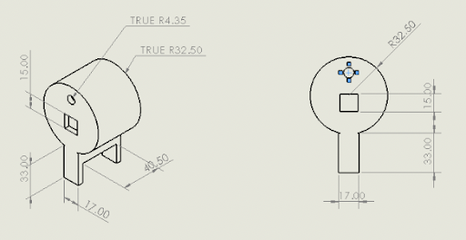 Head Module
The next part to be discussed is the XY connector seen in the image below along with the corresponding dimensions and measurements. This part is what allows the head module to move in the X-direction and in the Y-direction. The servo controlling the movement in the X-direction would be attached to the bottom, while the servo controlling the movement in the Y-direction would be attached to the upright face of the connector. The base and the upright face are 30mm wide to ensure that the servos can securely be drilled into the connector. There are also triangular support pieces to assist with stability and to maintain structural integrity of the device.
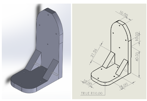 XY Connector
The final part to be discussed in this section is the lid of the box module seen in the image below with the measurements. The lid is 190mm X 140mm with a groove on the edges to securely fit inside the box. On the surface, there is a curved cut-out so that wires connecting to the sensors, servos and camera can connect to the Raspberry Pi and the breadboard. Located in the center of the box is a rectangular engraving which serves as an indicator as to where the servo controlling the X-direction will be mounted to.
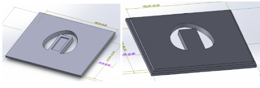 Lid Module
Finally, the image seen below is a representation of how all the components will be fitted together, excluding all the other electrical components.
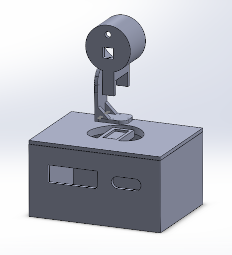 Finished Design
